So my previous two experiments got me excited to start working on the music videos for my forthcoming album Monstrum Pacificum Bellicosum. I will likely start releasing music from this album in April 2026 on Bandcamp, and hope to release the entire completed album on platforms such as Spotify, Apple Music, and Amazon Music in late December 2026. Once the album is released, I will also be releasing music videos for the individual tracks from the album.
That being said, I have already started working on creating rough drafts of the music videos for some of the tracks from the album. In January, the Carole-Calo Gallery will be hosting a a show of Stonehill faculty work. I hope to have first drafts of some (possibly all) of tracks from the album ready to go for inclusion in the faculty show in January. Likewise, Bleep Blorp 2026 will be on April 18th at Stonehill College. I hope to including some (possibly all) of the music videos for the album in a gallery show for Bleep Blorp 2026 as well.
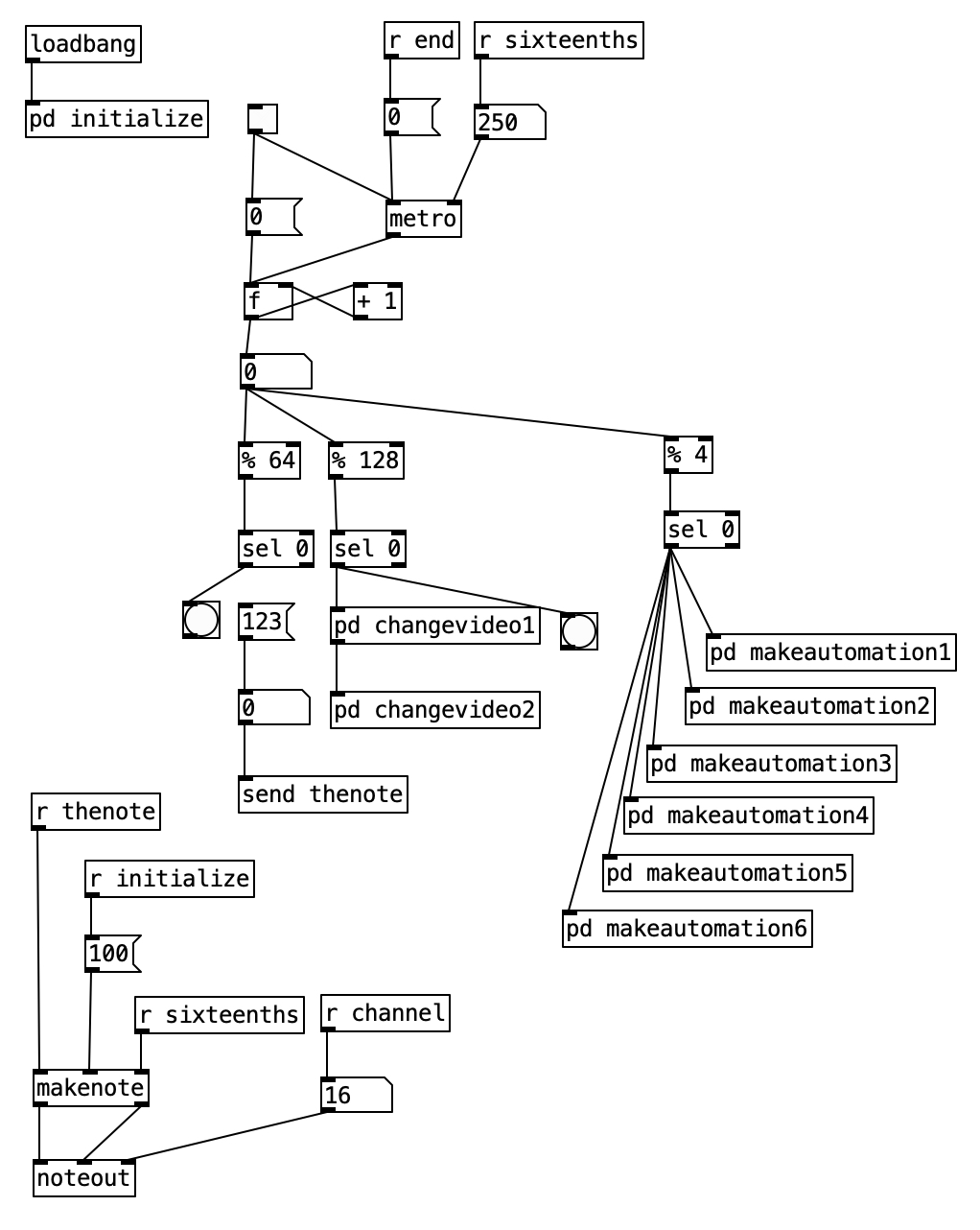
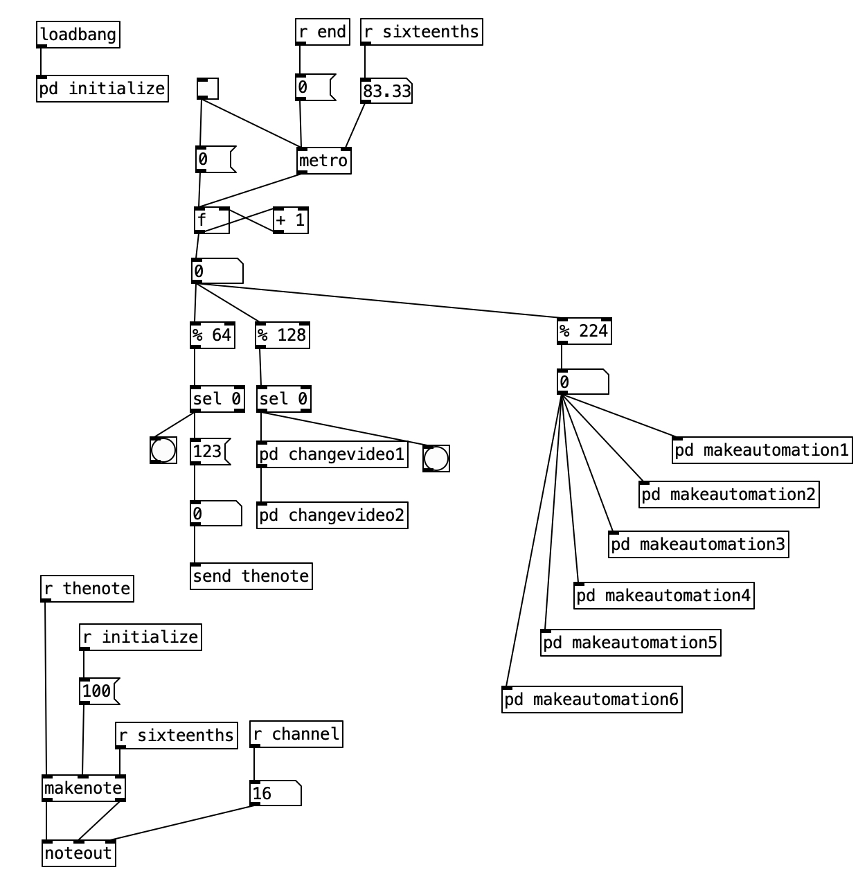
While I have had significant problems with controlling the Hypno through MIDI, I decided to control the video this way. I settled on this approach for two reasons. First, when paired with Pure Data, this approach offers precise timing, allowing the video to be well synchronized with the audio. Secondly, using MIDI allows me to control as many parameters at once as I want.
In comparison to my previous experiment, I wanted to art direct my work on this a bit more. The first decision I made was to keep the video processing far simpler for faster tracks on the album, and gradually move towards more intensive processing for slower tracks. This simplicity versus complexity is achieved in three ways. Fewer parameters are controlled in the simpler, faster tracks. I also restrict the range of outcome for parameters in the faster, simpler tracks. Finally, as the tracks become slower, and feature more complex processing, I also add in more possibilities for source video.
Monstrum Pacificum Bellicosum consists of 18 tracks, at nine different tempos. To put this another way, each tempo is used on two different tracks. Accordingly, each level of processing complexity is used for two tracks from the album.
The source video for Monstrum Pacificum Bellecosum all come from the 1925 silent film version of Sir Arthur Conan Doyle’s The Lost World. This film was the Jurassic Park of its day, featuring plenty of high quality stop motion animation of dinosaurs. I edited down to the stop motion animation of the film, and put this segments into 40 second phrases. resulting in 25 video phrases, although a couple of these phrases include non-stop motion shots to round out the 40 second phrases.
I selected the nine most active of these 25 video phrases to be the source material for the fastest tracks, both of which are at the tempo of 132 beats per minute. For each successive increase in complexity, each of which comes with a decrease in tempo, I will add two more of the original 25 video phrases. In addition, for each increase in complexity, I will also add seven more 40 second phrases comprised of footage derived from the previous tier of complexity.
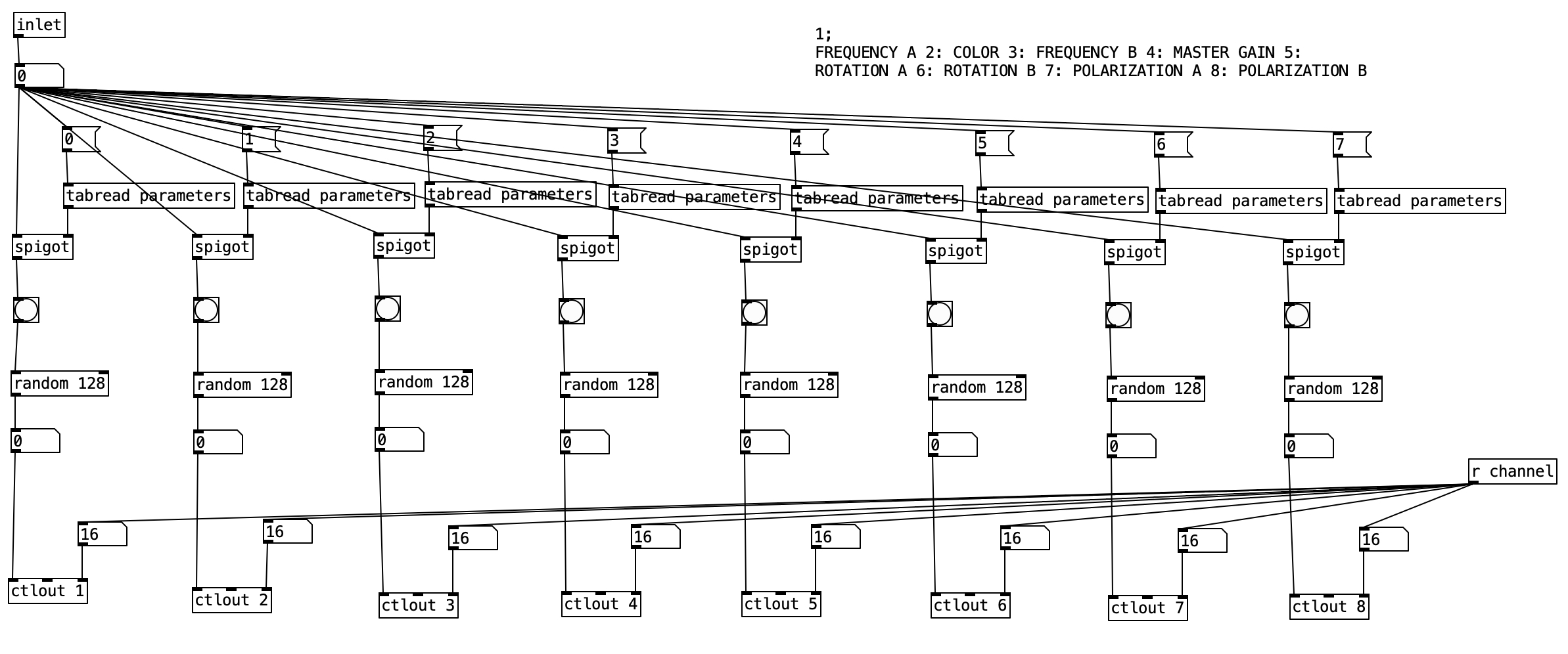
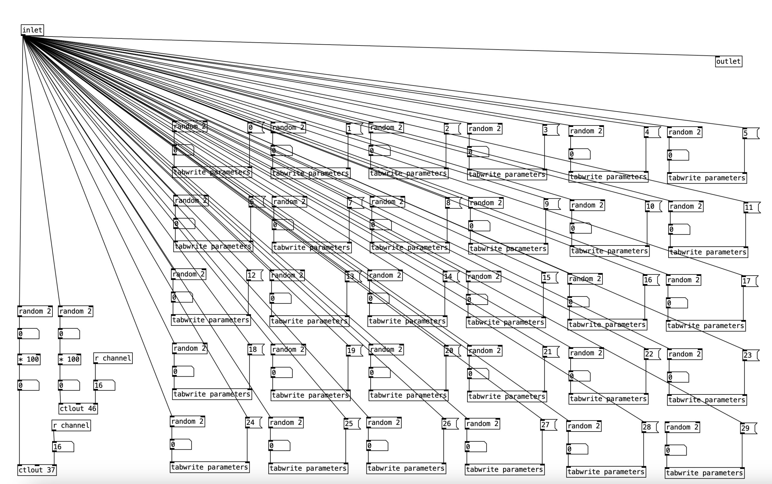
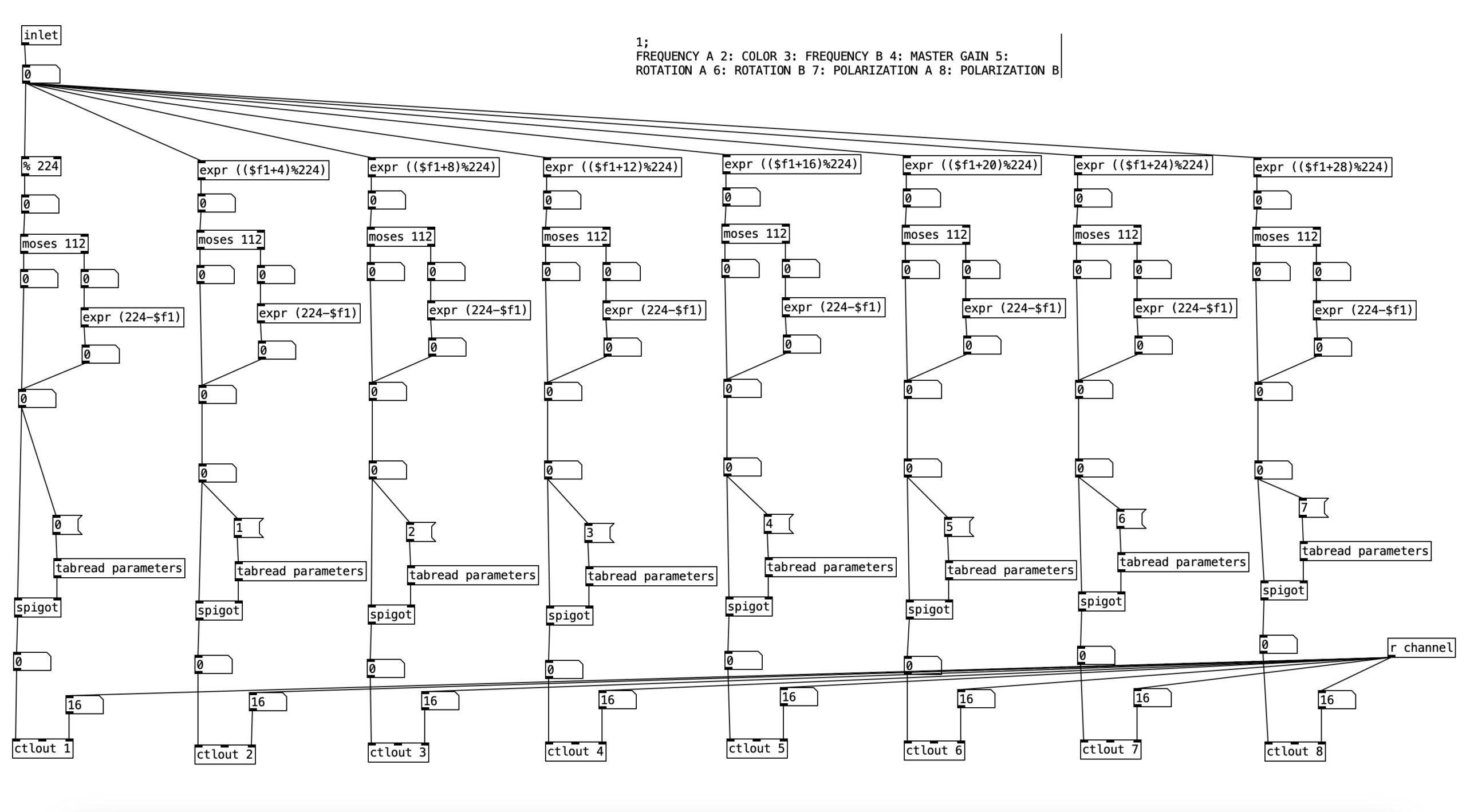
Another aspect that is used to create a sense of increasing complexity is the number of parameters manipulated. A video phrase is selected randomly at the beginning of each phrase for all videos. Likewise, the feedback mode is changed at the beginning of each phrase. For the fastest tracks, those at 132 bpm, the PureData algorithm only changes four additional parameters. These parameters include the master hue (color shift), the master gain, as well as the frequency for both oscillators A and B. Remember from a previous entry that frequency would be best understood as zooming in and out. At the beginning of every phrase, the algorithm changes which parameters will be changed in the phrase, with every parameter having a fifty percent chance of being selected.
Figure 1: The first 3 levels of complexity
| Complexity | Tempo | P1 | P2 | P3 | P4 | Range | T# | T# |
| 1 | 132 | Color | Gain | Freq A | Freq B | 4 | 8 | 16 |
| 2 | 120 | C. Offset A | C. Offset B | Sat. A | Sat. B | 8 | 5 | 15 |
| 3 | 112 | Rotate A | Rotate B | Polar A | Polar B | 16 | 6 | 18 |
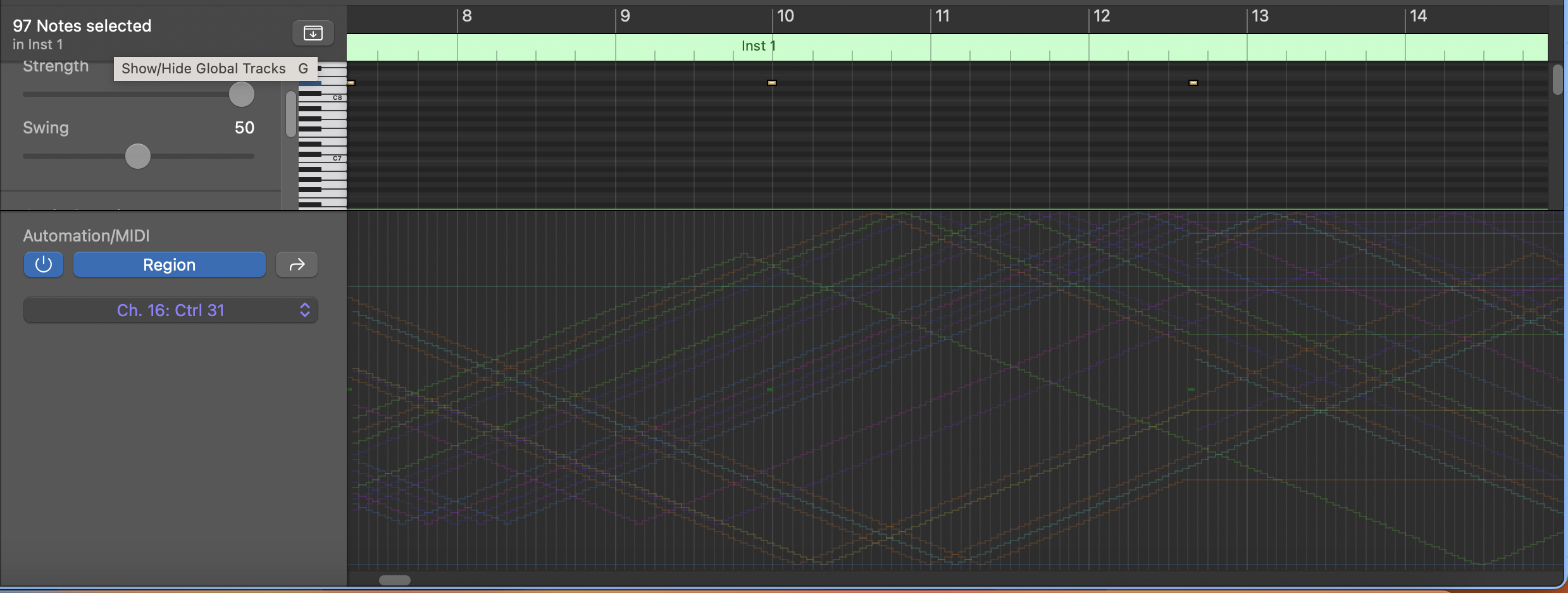
I also control the complexity of the manipulation by controlling the range of variation for the parameters. Initially I focus on changing parameters by using what is essentially a low frequency oscillator set to a triangle wave. For the fastest tracks, I have the period of this triangle wave set to repeat every quarter note. Because the algorithm is sending out new values every sixteenth note, that means that the parameters stay within a range of four values. Because MIDI is a seven bit protocol, that is the values range between 0 and 127, I center this range on 64 (the center value), save for the instance of the parameter of gain. When you put the gain control in the center, you are actually at a gain level of 0, as the lower half of the settings are negative gain levels, while the upper half are positive gain levels. So for the gain, I center this range on 96, which is halfway up on the positive gain levels.
To date, I have created first drafts for six videos, or three levels of complexity. The second level of complexity is for the two tracks at (or around) 120 bpm. To these tracks I also start manipulating the color offset and saturation levels for each of the two video oscillators. The period for the LFO triangle wave controlling these parameters is set to a half note, thus yielding a range of eight values for these parameters.
For the third level of complexity, the videos at or around 112 bpm, I added the parameters of rotation and polarization for each of the two video oscillators. Initially I had intended to have all twelve parameters to be controlled by a LFO triangle wave, but I found that the Hypno just couldn’t handle that much data, and started to make uncontrolled parameter changes. Accordingly, I only use the LFO triangle wave to control the four new parameters (rotation and polarization). The period for these triangle waves is a whole note, yielding a range of values of 16.
The remaining parameters, that is the parameters introduced in the previous two levels of complexity (color, gain, frequency, color offset, saturation), are randomly changed every beat. Again, these changes only occur when that parameter is set to change during a given phrase. To match the complexity of the other four parameters, the range for these random changes is 16.
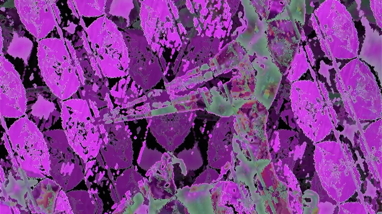
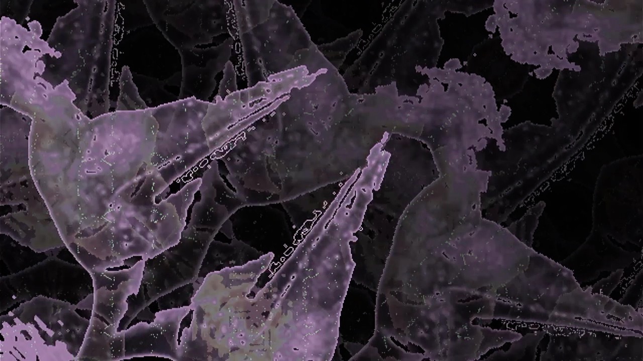
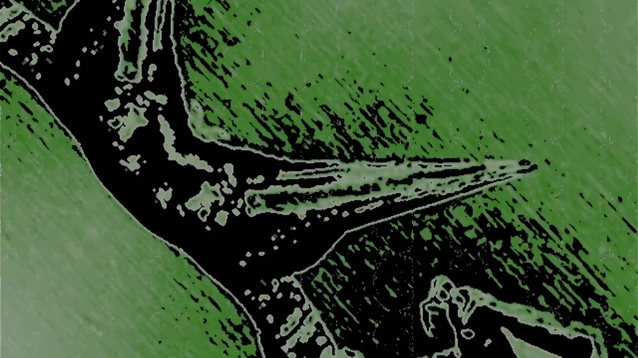
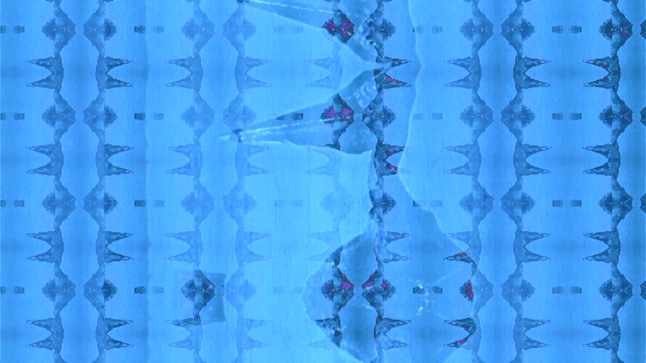
Figure one is a basic summary of the first three levels of complexity for the videos for Monstrum Pacificum Bellicosum. The final two fields in the table are the track numbers that correspond to that complexity level. While I have completed drafts of these four tracks (5, 6, 8, 15, 16, and 18), I will not be sharing them early, as I want them to be a surprise for both the gallery show, as well as when I ultimately post them online when the album is complete. That being said, I do want to leave readers with some visual fun, so I’ve included some screen shots from the first draft of some of these six videos. In the interest in highlighting how these parameters can create variety, I have selected screen shots that are all manipulations of the same image of a pterodactyl.
I plan on doing more updates as I complete more videos. In this report I have made the decision to not include any PureData code, as all the code I’m using to create these videos is essentially derived from code I have already presented.
Screen shot from video draft for Windghost (monster 5)
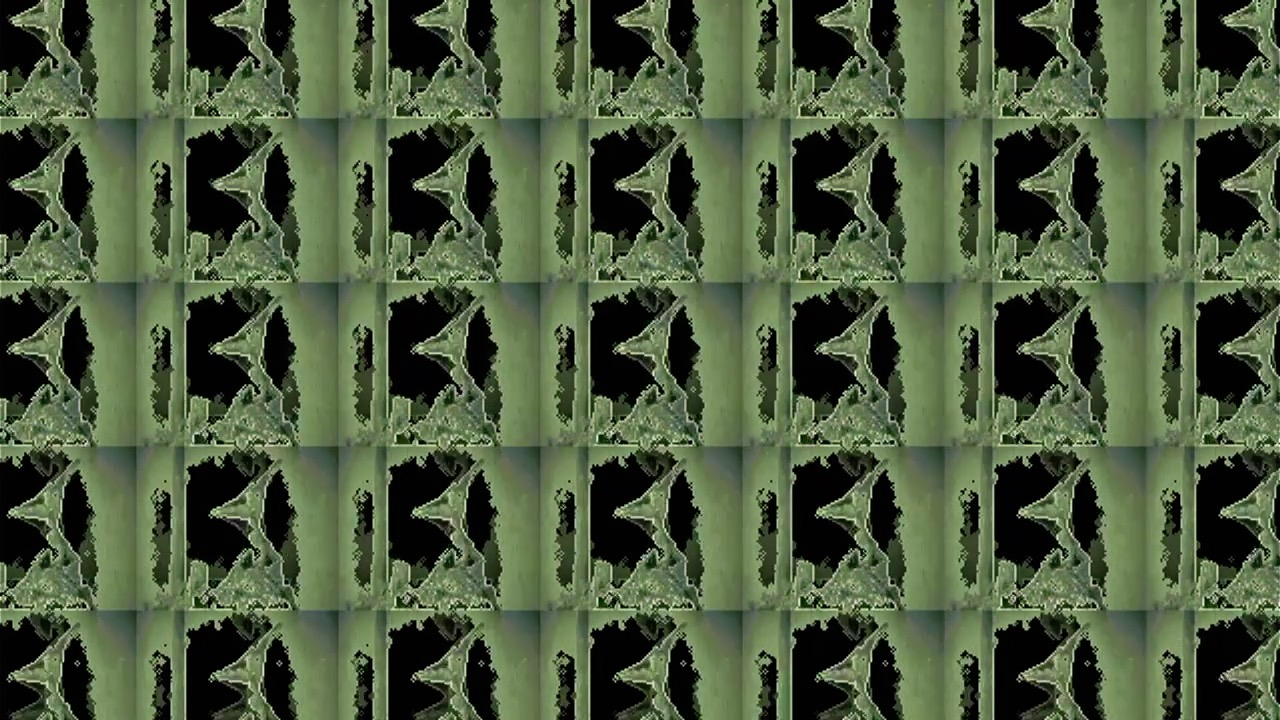
Screen shot from video draft for Windghost (monster 5)
Screen shot from video draft for Windghost (monster 5)
Screen shot from video draft for Megalodon (monster 15)
Screen shot from video draft for Moonbeast (monster 16)
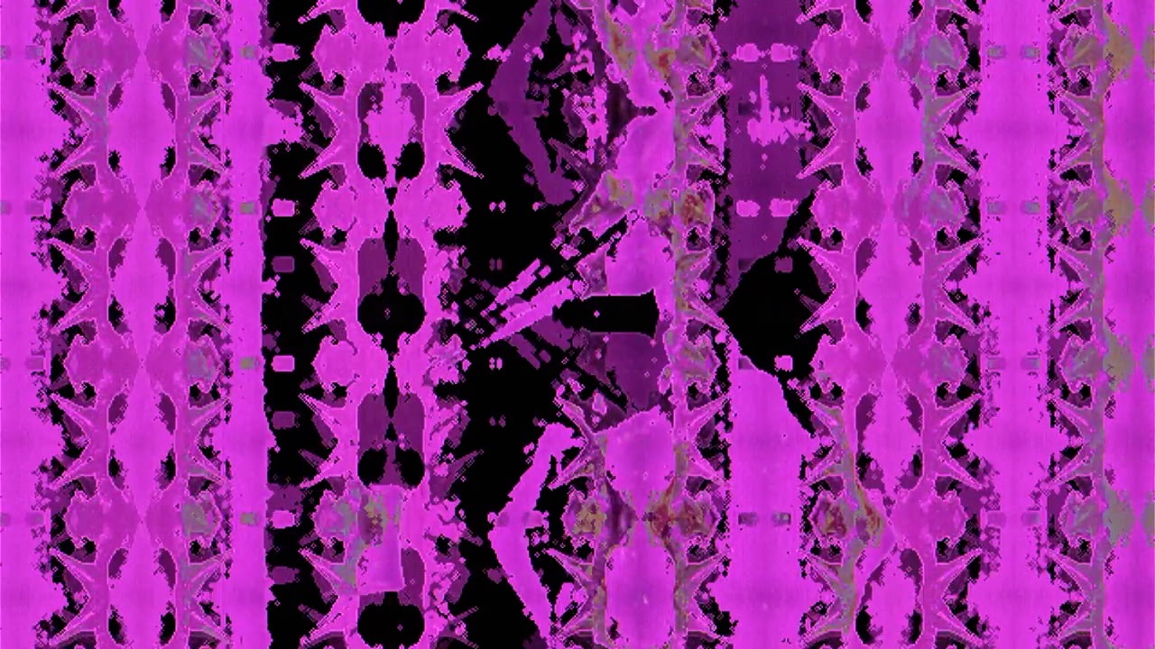
Screen shot from video draft for Rukarazyll (monster 18)