Digital Innovation Grant: July 18th Update

Wow. It’s been a long time. An embarrassingly long time. Some of my excuses are typical academic excuses: busy spring 2025 semester, conference presentation due date, and busy summer 2025 semester. However, a couple of them have been personal: my mother had a stroke and my elder cat has had a lot of health problems, and is likely in his last months.

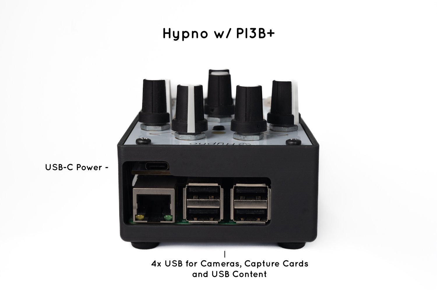
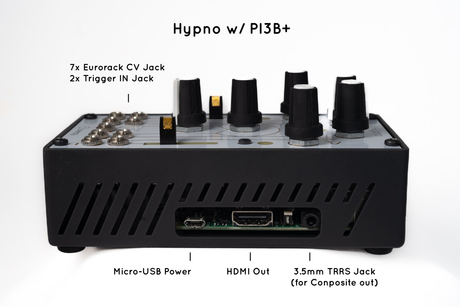
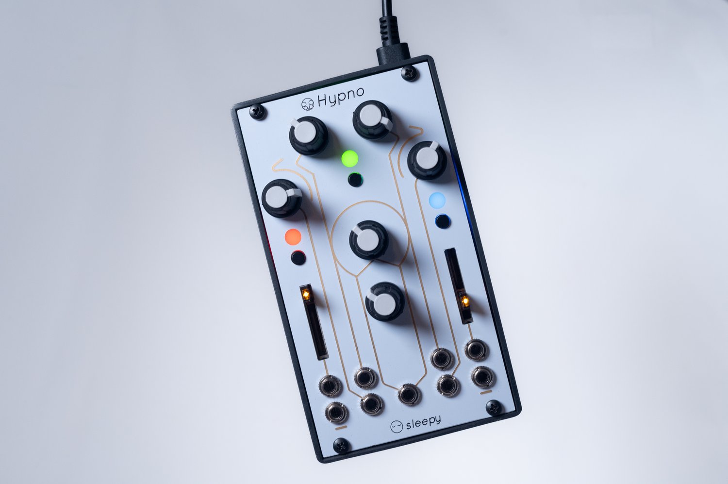
Another thing holding up the process was the final funds. I received the final funds in June, and was able to purchase the remaining items. However, I altered the list a bit, as it seems the primary student use of the video synthesis setup will be students in VPM 248: Sound Synthesis. Accordingly, I purchased some Eurorack gear that will work in combination with the Sleepy Circuits Hypno, as well as some accessories.

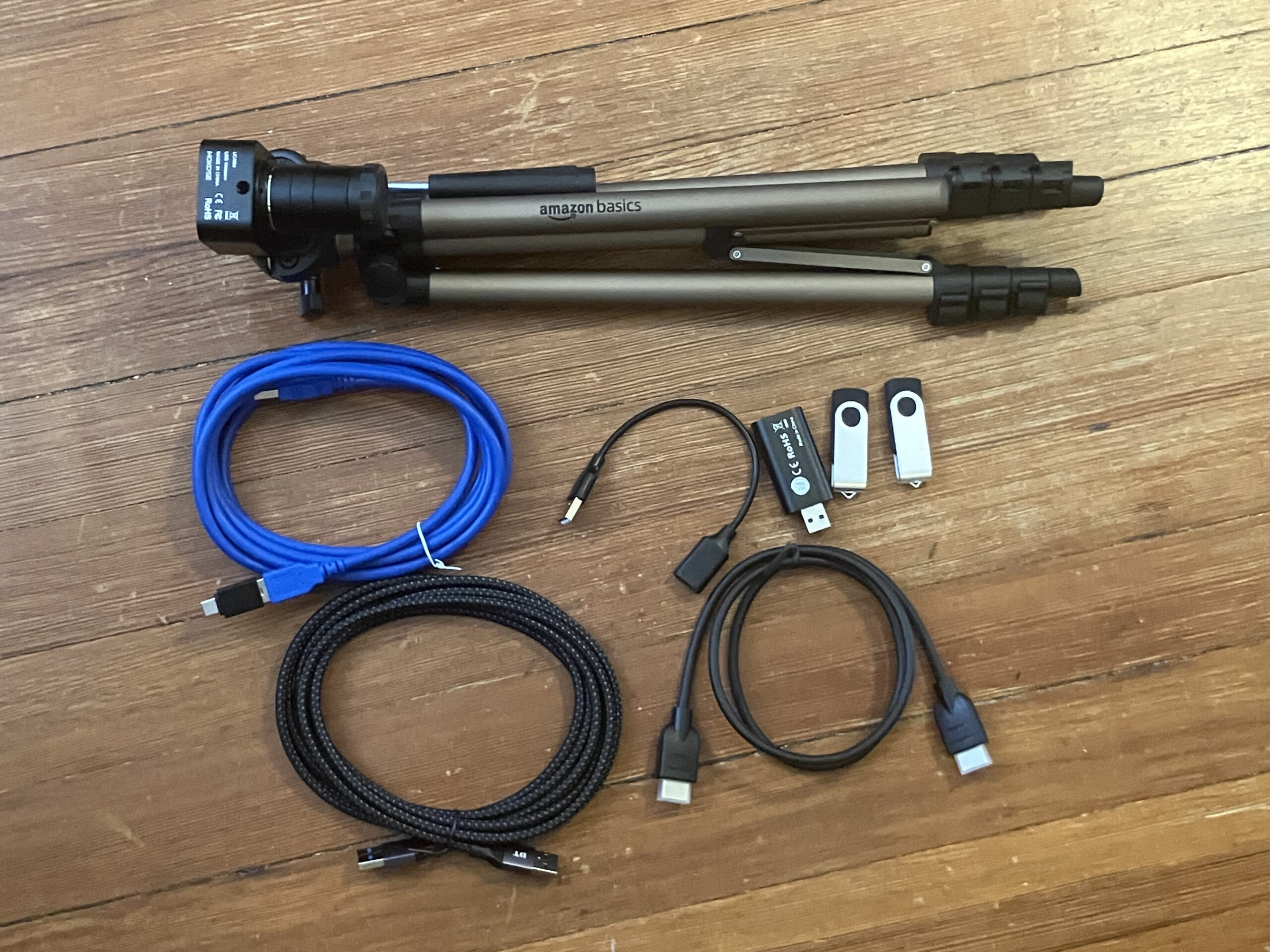
In terms of the accessories, I bought a decent USB webcam with manual zoom and manual focus, a tripod, a USB HDMI capture card, a few of USB cables and two USB thumb drives. The camera is a MOKOSE HD webcam with a 5-50mm zoom lens. The lens is a CS-mount lens that can be removed and replaced with other CS-mount lenses.

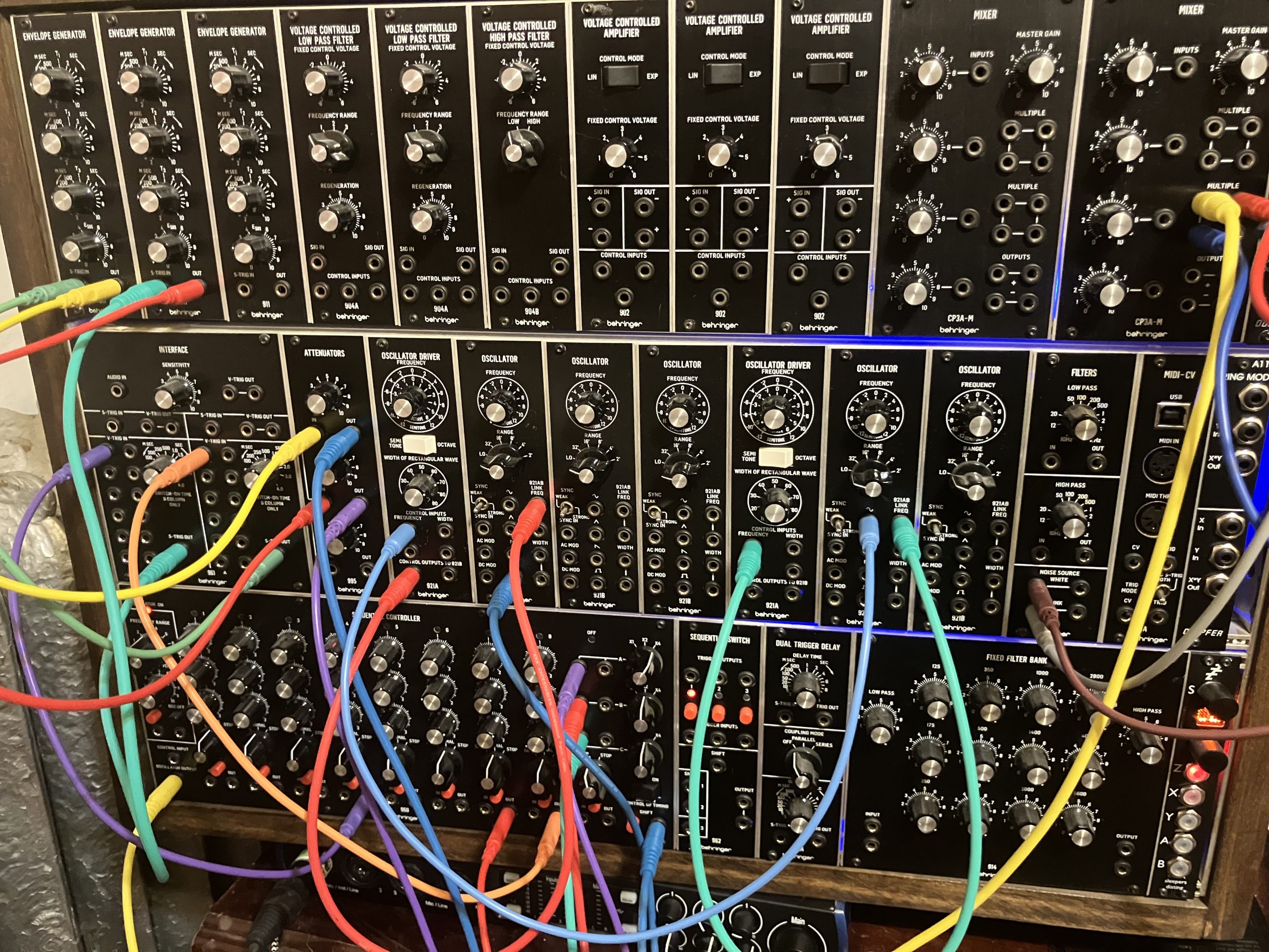
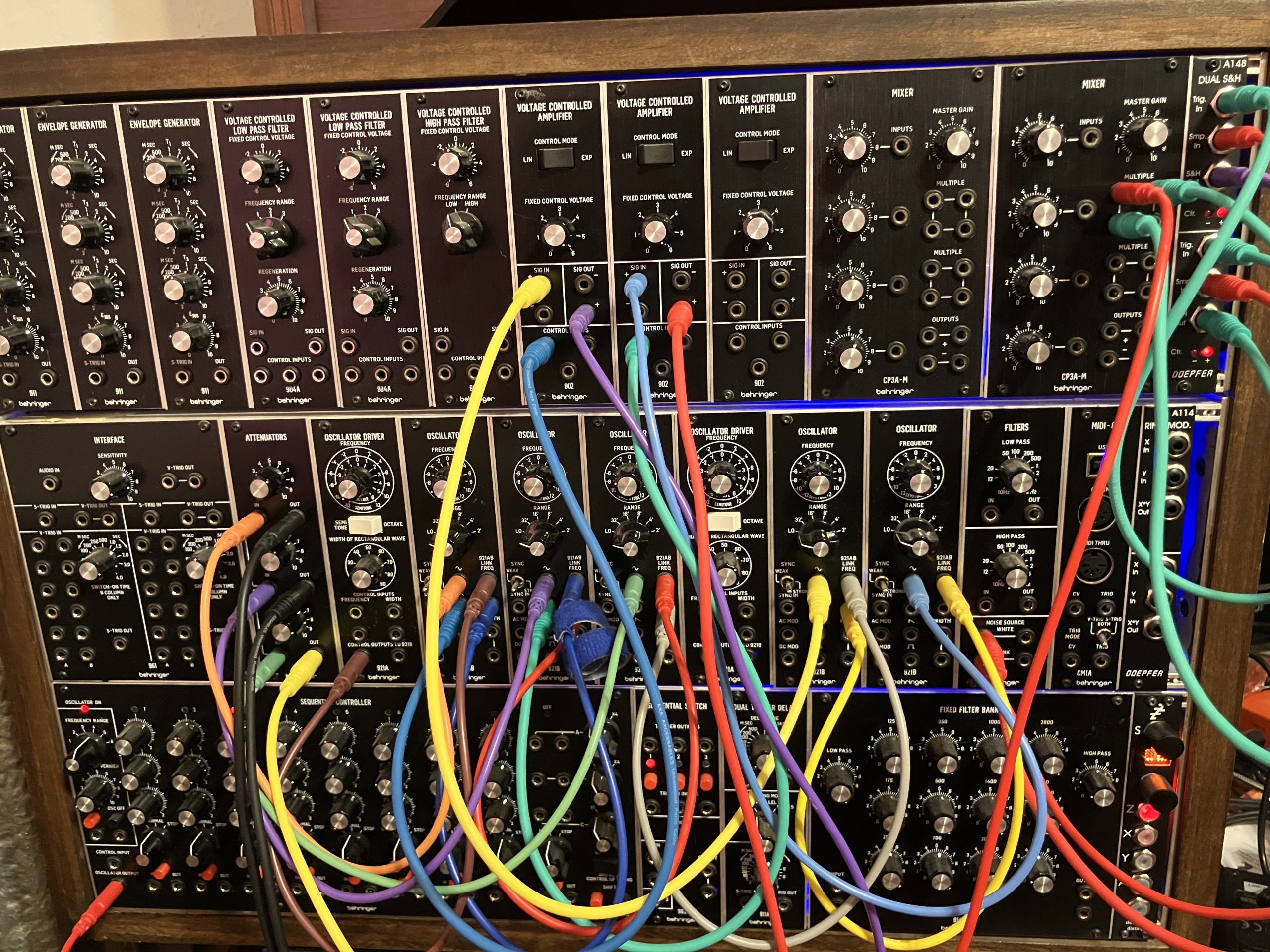
The Eurorack setup is perhaps of greater interest. In the previous entry, I went into detail how Eurorack modules can be used to control the settings of the Sleepy Circuits: Hypno. The setup includes a Behringer 960 sequential controller, a Behringer CP3A-M mixer, and a Behringer Four LFO enclosed in a Cre8audio NiftyCASE. In addition to these items I purchase a set of 5 patch cables, and some rack screws.

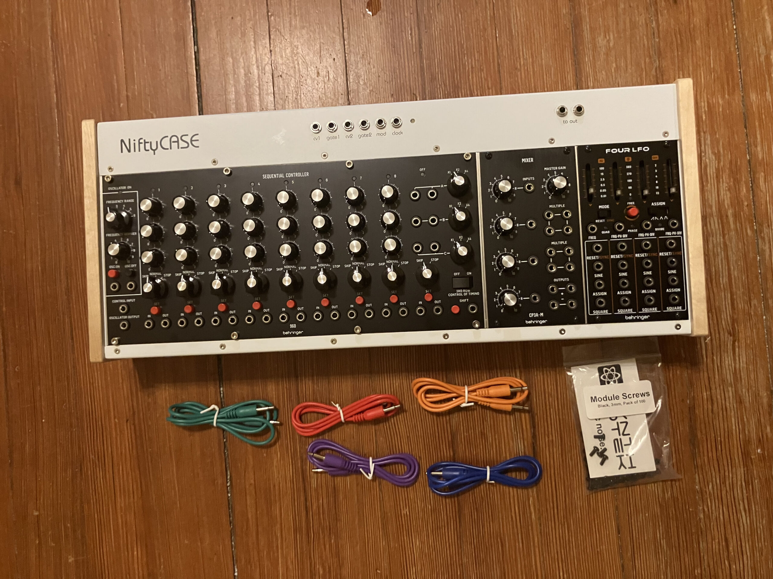
The NiftyCASE provides power to the three modules, but also allows for MIDI input via 5-pin DIN, as well as USB. Any MIDI input is then converted to control voltages by the NiftyCASE. The Four LFO contains four low frequency oscillators each of which can output sine, square, sawtooth, ramp, triangle, or trapezoidal waves at frequencies that are suitable to for controlling other modules.

The other two modules (the 960 and the CP3A-M) are recreations of modules from the Moog 900 series of the late 1960s and early 1970s. The 960 Sequential Controller features three rows of eight knobs, each of these knobs is used to set a different frequency. These set frequencies are then played back, looping from the left to right. To the right of these knobs are control voltage outputs for each row. These voltages can then be used to control other modules (for instance the Hypno). In addition to having a speed control, the 960 allows each of the 8 steps to be in play, skip, or stop mode. In play mode, the step is played, and then moves onto the next step. In skip mode, that step is skipped. In stop mode, when that step is hit, it repeats until it is switch to either play or skip mode.

The CP3A-M is a mixer, but it has a few nice features. If you use only one input, you can use it as an attenuator, that is as a module that can decrease the amplitude of a signal. Likewise, since it has both positive and negative outputs, it can be used as a signal inverter. Finally, in addition to being a four channel mixer, it contains two sets of multiples. Multiples can be used to split a given signal into two or three duplicate copies of the same signal.

Starting in spring 2026, students enrolled in VPM 248: Sound Synthesis will be required to create a music video for their first project using the Hypno in conjunction with the above Eurorack setup. Examples will be presented in the music technology showcase. One additional benefit of this Eurorack setup is that it will also work in conjunction with several of the synthesizers resident in The Song Factory, the music program’s recording studio.

In addition to incorporating this gear into VPM 248 I still have more work outstanding for the Digital Innovation grant. I have to finish music videos for the first two tracks on my album Point Nemo. I also have to organize a concert of live music that will feature my student assistant performing video live using the Hypno in conjunction with the Eurorack setup. I hope to get the two videos done before the beginning of Fall 2025, and I imagine I may be able to schedule the concert for mid November 2025.

Digital Innovation Grant: March 14th Update

Well, color me excited. Spoiler alert, this experiment was pretty darned successful for a few reasons. I’ll save those reasons for later in the post (that’s what we call a teaser in the business). The experiment at hand was to create a music video for the third track of Point Nemo using control voltages to automate settings on the Hypno. While my previous experiment also entailed using control voltages to automate parameters of the Hypno, that experiment focused on smooth flowing changes provided by sine waves.

For this experiment I focused on instantaneous changes primarily using a step sequencer. In particular, I used Behringer’s clone of Moog’s classic 960 sequencer (lower left in the image below). Since control voltages are literally just voltages that are applied to individual modules in order to alter a setting or parameter, a step sequencer is typically a series of knobs or sliders that are used to set individual voltages. These voltages can then be stepped through in sequence, potentially providing a melody or another repeating musical function.

The Moog 960 has three rows of eight knobs. Each row has two identical outputs. Accordingly, when the 960 is being used, it can output three different sequences of voltages. Furthermore, each row has a multiplier switch with three modes, 1x, 2x, and 4x. Thus, each successive setting generates a wider range of voltages. The speed of the 960 can also be controlled by sending individual gate signals to the shift control on the module’s lower right side. Since a gate signal is just an on or off signal, you can actually use a low frequency oscillator set to a square wave to provide a chain of gate signals. To make things even more complicated, I controlled the frequency of this low frequency square wave with a low frequency sine wave, resulting in the tempo increasing and decreasing in an undulating wave.

As mentioned in the previous experiment, that Hypno has seven CV inputs. The three outputs of the Behringer 960 covers three of these. I covered another two of them by using the same sample and hold setup that I mentioned in the previous experiment, including one being fed pink noise and the other being fed white noise.

The final two control voltages sent to the Hypno came from envelope generators (EG). Envelope generators are intended to provide sculpted sound settings that approximate the nature of acoustic sound. Most envelope generators reduce sound into four stages: attack (the time it takes for a sound to hit full volume), decay (the amount of time it takes for a sound to come down from full volume), sustain (the level at which a sound sustains when it is being held), and release (the time it takes for a sound to become inaudible).

Envelope generators are triggered by a gate signal. Fortunately, the 960 has gate outputs for each of the eight repeating steps of the sequencer. Thus, I attached the fourth gate to one EG and the eighth to another EG. I then fed each EG to its own attenuator to allow me to easily increase or decrease the effect of each. One of these two envelope generators was used to control the zoom control of oscillator B of the Hypno, which is very noticeable, causing the size of the shape generated by oscillator B to grow and decrease in a very rhythmic, predictable manner.

Since this experiment is focused on instantaneous changes, I decided to also use one of the two gate inputs for the Hypno. In particular, I fed yet another gate output from the 960 to the gate input for oscillator B of the Hypno,. This cycles the shape control for the second oscillator of the Hypno.

As stated earlier, I found the results of this experiment to be highly satisfying. First off, the use of the step sequencer provided a visually rhythmic result, which somewhat balances visual variety and consistency. This made improvising with the system a lot more manageable. The system itself provided most of the variety, leaving me to make an occasional tweak to keep things interesting.

For the video input I used a USB drive that had both the video that I used to create the previous experiment, as well as the video of that experiment. Thus, when improvising live with the system I regularly switched back and forth between the original (unprocessed) footage of the sun glinting off of waves of the ocean, and the heavily processed video of that footage that appears in the music video for the last track of the album. Thus, in this video the viewer can still frequently recognize the source of the video, namely the sun shining on waves. I also regularly changed the setting for the type of feedback used by the Hypno. Finally, I often found changing the overall hue and saturation levels of the Hypno to create satisfying results. To summarize what I’ve learned from this, if you use automation to control various parameters in an effective way, this greatly reduces the task of performing other changes live, allowing the improvisor to focus on just a few parameters.

The final satisfying element of this experiment is that I did not have a single connection drop in the HDMI cable, so I was able to record the entire video in a single pass, requiring minimal editing when assembling it into a music video. This really approaches my goal of being able to create a perfectly adequate music video nearly in real time. Now I can shift some of my focus in learning how to use the parameters of the Hypno in a variety of ways, so each music video can be somewhat unique rather than seeming like a cookie cutter of every other video I create using the Hypno.

Digital Innovation Grant: March 13th Update

While I am satisfied with my video for my improvisation on “The Star-Spangled Banner,” I recognize one potential area of improvement. Given that I have two hands I can, at most, turn two knobs on the Hypno at a time. However, given the complexity of the system, I am more likely to move only one knob at a time, particularly given that many parameters require the user to press one or more buttons while turning a knob.

Thus, it is useful to automate parameters on the Hypno to allow for complex, simultaneous parameter changes. Frankly, it is also worth learning how to do this in order to fully comprehend the potential applications of the system. There are two ways to automate settings on the Hypno. One is using control voltages (CV) from Eurorack compatible modular synthesizers. The other is through MIDI (Musical Instrument Digital Interface).

In December, 2024, I released an collaborative album of drone music titled Point Nemo. The album contains four tracks. My plan is to make music videos for all four tracks using the Hypno. For the final two tracks of the album I plan on automating parameters using control voltages, while the first two tracks I will automate settings via MIDI. I will create the music videos in reverse order, using footage from the previous video as the source. Accordingly, as the videos for the album progress, it should make a marked movement from heavily processed to less processed video, revealing a glimpse of the initial source video at the very end. I shot the source video at West Beach in New Bedford, shooting the late afternoon sun glistening off waves in the ocean. This source video relates directly to the title of the album, as Point Nemo is a location in the Pacific Ocean that is farthest from any existing land mass. Namely, it is equi-distant from Ducie Island in the Pitcairn Islands group, Motu Nui off the coast of Easter Island, and Maher Island which is off the coast of Antartica.

For the experiment at hand, I am using control voltages in conjunction with the Hypno to manipulate the source video, in turn creating video for the final track of the album, 364F234F6231. Before I get into the thick of it, let me return briefly to the topic of control voltages and modular synthesis. In the late 1960s, the earliest commercially available synthesizers were a series of individual modules that were packaged together. Each module typically performs a single function, and in order to make a sound of even the most basic level of sophistication, the user would have to route audio and control signals from several modules together using patch cables. The control signals would allow one module to control another through varying voltages. While such a means of making sound may seem antiquated and difficult, the complexity and nearly endless customization of such a system led to this approach, modular synthesis making a resurgence starting in the mid 1990s.

Perhaps suitably, the synthesizer I am using for this experiment is a modern clone of a modular synthesizer manufactured by the R. A. Moog Company in the late sixties and early seventies, the System 55. The instrument I have assembled over the years features, amongst other things, five oscillators and a step-sequencer. The Hypno features seven CV inputs as well as two gate inputs (gate signals are on or off signals that are useful for indicating things such as a key being depressed on a keyboard). For this experiment I only used the seven CV inputs.

Accordingly, I needed to feed seven control signals from my System 55 to the Hypno. Five of these come from the oscillators. All five oscillators were put in low frequency mode, that is the waveforms are slow enough that they do not produce audible pitches. Also, in all five cases I used the sine wave output. Three of these control signals were fed to attenuators, so I can easily reduce the amount of signal of each being sent to the Hypno. The other to sine wave signals were sent to voltage controlled amplifiers (VCAs). These VCAs can also be fed a control signal that automates how strong the signal is coming out of the module. That is, the control signal makes the volume louder or quieter. In this case, I controlled the VCAs using triangle wave outputs from two of the other oscillators. The output from the VCAs were then sent to the Hypno.

In this experiment I wanted to focus on smooth, flowing changes. Hence, my use of sine waves, which lends the resulting video a wiggly nature. However, in order to send voltages to all seven the Hypno’s CV inputs, I took a different approach with the remaining two signals. Namely I used the oscillator output of the step sequencer. This can be thought of as a gate signal that works like a metronome, providing a steady beat. This signal was sent to two different sample and hold circuits. While the dual sample and hold module I have in my setup is not technically from the line of System 55 clones, the original Moog System 55 did feature a sample and hold circuit.

So, what is a sample and hold circuit? You feed it an input, and a gate signal. Every time the module receives a gate signal, it samples the voltage at the input at that moment, and it holds the output signal at that level until the next gate signal is received. The most common usage of a sample and hold circuit is to feed it a noise signal, which is essentially random voltages. When used in this manner the module produces steady, but random voltages that change at a steady pulse.

That is exactly what I did here, except I fed one of the sample and hold circuits pink noise while I fed the other white noise. Pink noise has less high frequency content than white noise. The result of this difference is that a sample and hold circuit being fed pink noise will have a more limited range of output than one using white noise. Regardless, the two sample and hold circuits produce instantaneous (sudden) changes which were then sent to the Hypno.

Just as had happened with the making of my Star Spangled Banner video, the HDMI connection between the Hypno and my HDMI to USB capture card frequently broke. Thus, rather than generating a continuous twenty and half minute video, I generated five different videos ranging in length from about a minute and a half to ten minutes long. I generally arranged the video from most heavily manipulated to least manipulated. Throughout the video I feel that there are moments where one can recognize that the source video is sunlight glinting off of ocean waves. As stated earlier, my next video experiment will also use control voltages for automation, and will use the results of this experiment as the video input, so you’ll want to stay tuned for that.

Using the Hypno 6: Advanced Mode

When not using input shapes, you may press the same combination of buttons (A & B for oscillator A or B & C for oscillator B) to set some advanced parameters. Some of these are the same as those used for input shapes. For instance, knobs E & F are used to set the luma key maximum (E) and minimum (F) of a given shape. Likewise, the farthest away of the top knobs (knob D for oscillator A and knob A for oscillator B) are used to squash or stretch the vertical dimension of a shape. However, when using the poly shape, this control is used to set the number of sides for the polygon. In this mode the three nearest knobs (knobs A, B, & C for oscillator A and knobs B, C, & D for oscillator B) are not mapped to any parameter.

Again, regardless of which oscillator is being adjusted, the slider on the left (A) performs a crop on the X axis, while the slider on the right (B) performs a crop on the Y axis. However, when the sine or tan shapes are being used, the slider on the left (A) adds extra modulation on the opposite access, while the slider on the right (B) adjusts the waveshape of the modulation.

Here’s a Sleepy Circuits quick guide describing some of the controls available in Advanced Mode . . .


video by Sleepy Circuits

The Hypno has still more features such as Eurorack patching, MIDI control, and presets. Further information can be found out about these features from the Sleepy Circuits website as well as on their YouTube channel.

Using the Hypno 5: Using Input Shapes

The Hypno will accept video via USB. This could be a USB webcam, an HDMI camera plugged into a HDMI to USB capture card, or a USB thumb drive that contains video files. Note that input shapes can be used on both oscillators simultaneously. You can change parameters affecting the live input by pressing two buttons. To do this for oscillator A, press buttons A and B, to affect oscillator B you would press buttons B & C.

The most fundamental of these controls is the input index and folder control. These controls are knobs A & B for oscillator A, and knobs C & D for oscillator B. The outermost knob controls the index (knob A for oscillator A and knob D for oscillator B). Moving this knob to the left most counter clockwise position can allow you to switch between two distinct video inputs. When using a USB drive including numerous video files, the inner most knob (knob B for oscillator A and knob C for oscillator B) navigates the folder, while the index (knob A for oscillator A and knob D for oscillator B) navigates the files. If you want to see the file names while you are navigating, you can first turn on help mode by holding buttons A & C down while turning knob F to the right past twelve o’clock. You can turn help mode off by holding down the buttons A & C while moving knob F to the left past twelve o’clock.

Help Mode Quick Guide

video by sleepy circuits

The third knob from the oscillator (knob C for oscillator A and knob B for oscillator B) are inactive in this mode. The farthest knob from a given oscillator (knob D for oscillator A and knob A for oscillator B) control the aspect of video, with the 12 o’clock position being normal. Moving the knob to the right stretches the video vertically, while moving the knob to the left squashes the vertical dimension of the video.

Regardless of which oscillator is being adjusted, the top center knob (knob E) controls the luma key max setting, while the lower center knob (knob F) sets the luma key minimum value. When the minimum is set higher than the maximum, the luma key values invert. In essence, luma key values allows you to make a portion of a visual image transparent, based upon the color value. Likewise, regardless of which oscillator is being adjusted, the left slider (slider A) performs a crop of the image on the X axis, while the right slider (slider B) performs a crop of the image on the Y axis.

Here’s a Sleepy Circuits quick guide for using video input . . .


video by Sleepy Circuits

Here’s a useful quick guide by Sleepy Circuits showing how to prepare video and image files for use on a USB drive . . .


video by Sleepy Circuits

Using the Hypno 6: Advanced Mode

Using the Hypno 1: Connections

The Sleepy Circuits Hypno is a video synthesizer that can generate video using two video oscillators that generate a variety of shapes shapes. Each video oscillator can be manipulated using a series of buttons, sliders, and dials. The Hypno can also accept video input via USB for each of the two video oscillators, allowing it to manipulate video (live or pre-recorded) in real time. Sleepy Circuits has a lot of great info about how to use the Hypno spread between the manufacturer’s website and their YouTube channel. However, in my opinion, they lack a single resource that functions like a full manual taking you through how to use the Hypno from beginning to end. I hope to do this in a few blog entries.

Let’s start off by looking at inputs and outputs. The back face of the Hypno features four USB inputs that can be used for connecting cameras, capture cards, USB drives, and MIDI instruments. The right hand side of the module features an HDMI out, a composite out, and a micro USB port which is used to power the unit. The Hypno is a bit picky in terms of the order you plug things in. You should always plug in the HDMI out before plugging in the power. When you plug in the power, you will notice that the Hypno goes through a boot up process. Note that there is no power switch, so turning the unit on and off is done through plugging it in and unplugging it. If you are going to use any USB input, you would plug that in third, after plugging in the power.

image from Sleepy Circuits.

image from Sleepy Circuits.

The face of the Hypno features two sliders, three buttons, and six dials. Since each of these fulfills several functions, none of them are labelled. The face also has nine 3.5mm TS sockets for use with Eurorack and Eurorack compatible gear. These nine ports can be used to control / automate the two sliders, two of the three buttons, and five of the six dials. We’ll spend more time dealing with this in a future post. However, if you plan on using these Eurorack connections, you will want to connect them after connecting power.

image from Sleepy Circuits.

At this point, you should be able to correctly connect the Hypno to inputs, outputs, and power in the correct order.

Using the Hypno 2: Performance Mode

Sabbatical: Week 1 Update

The first week of my sabbatical went better than I had expected. I managed to record all of the theremin parts I had hoped to, leaving me a week ahead of schedule. All in all I recorded 13 phrases:

1 phrase for Tristar
1 phrase for 737
1 phrase for A300
3 phrases for DC-8
1 phrase for 727
1 phrase for 707
1 phrase for DC-10
2 phrases for DC-9
2 phrases for 747

The majority of these phrases were recorded using a Moog Etherwave Plus to control a Behringer System 55, which is a clone of the Moog modular synthesizer from the early 1970s. A few of the phrases were recorded using the Etherwave Plus to control a small Eurorack synthesizer centered on the 2HP Vowel formant synthesizer and a the Calsynth Monsoon granular synthesizer. One of the tracks was recorded using just the Etherwave Plus, yielding a traditional theremin sound. Below you can see a patch on the system 55 using four oscillators, a low pass filter, and a VCA.

Due to the new tracks, I’ve re-released recordings of TriStar, 737, and 707. As mentioned in my previous post, I had about a month of data loss. I managed to recover the string arrangements I wrote for TriStar, A300, DC-8, & DC-10, and wrote string arrangements for Rotate 737, 727, 707, DC-9. & 747. Thus, all the arrangements are completed. They only need to be formated for printing so I can send them out to the string quartet that will be recording them. Also relevant to the discussion is my left ear is healing nicely. It may not be at 100% yet, but it is getting there.

Given that I am one week ahead in my schedule, I’m revising my schedule thusly . . .

1 Theremin
2 Bass harmonica
3 Bass harmonica
4 Fretless
5 Fretless
6 Pedal Steel
7 Pedal Steel
8 Strings
9 Trombone
10 Trombone
11 Taishogoto
12 Cello
13 Voice
14 Lyricon
15 Modular Synth