
While I am satisfied with my video for my improvisation on “The Star-Spangled Banner,” I recognize one potential area of improvement. Given that I have two hands I can, at most, turn two knobs on the Hypno at a time. However, given the complexity of the system, I am more likely to move only one knob at a time, particularly given that many parameters require the user to press one or more buttons while turning a knob.
Thus, it is useful to automate parameters on the Hypno to allow for complex, simultaneous parameter changes. Frankly, it is also worth learning how to do this in order to fully comprehend the potential applications of the system. There are two ways to automate settings on the Hypno. One is using control voltages (CV) from Eurorack compatible modular synthesizers. The other is through MIDI (Musical Instrument Digital Interface).
In December, 2024, I released an collaborative album of drone music titled Point Nemo. The album contains four tracks. My plan is to make music videos for all four tracks using the Hypno. For the final two tracks of the album I plan on automating parameters using control voltages, while the first two tracks I will automate settings via MIDI. I will create the music videos in reverse order, using footage from the previous video as the source. Accordingly, as the videos for the album progress, it should make a marked movement from heavily processed to less processed video, revealing a glimpse of the initial source video at the very end. I shot the source video at West Beach in New Bedford, shooting the late afternoon sun glistening off waves in the ocean. This source video relates directly to the title of the album, as Point Nemo is a location in the Pacific Ocean that is farthest from any existing land mass. Namely, it is equi-distant from Ducie Island in the Pitcairn Islands group, Motu Nui off the coast of Easter Island, and Maher Island which is off the coast of Antartica.
For the experiment at hand, I am using control voltages in conjunction with the Hypno to manipulate the source video, in turn creating video for the final track of the album, 364F234F6231. Before I get into the thick of it, let me return briefly to the topic of control voltages and modular synthesis. In the late 1960s, the earliest commercially available synthesizers were a series of individual modules that were packaged together. Each module typically performs a single function, and in order to make a sound of even the most basic level of sophistication, the user would have to route audio and control signals from several modules together using patch cables. The control signals would allow one module to control another through varying voltages. While such a means of making sound may seem antiquated and difficult, the complexity and nearly endless customization of such a system led to this approach, modular synthesis making a resurgence starting in the mid 1990s.
Perhaps suitably, the synthesizer I am using for this experiment is a modern clone of a modular synthesizer manufactured by the R. A. Moog Company in the late sixties and early seventies, the System 55. The instrument I have assembled over the years features, amongst other things, five oscillators and a step-sequencer. The Hypno features seven CV inputs as well as two gate inputs (gate signals are on or off signals that are useful for indicating things such as a key being depressed on a keyboard). For this experiment I only used the seven CV inputs.
Accordingly, I needed to feed seven control signals from my System 55 to the Hypno. Five of these come from the oscillators. All five oscillators were put in low frequency mode, that is the waveforms are slow enough that they do not produce audible pitches. Also, in all five cases I used the sine wave output. Three of these control signals were fed to attenuators, so I can easily reduce the amount of signal of each being sent to the Hypno. The other to sine wave signals were sent to voltage controlled amplifiers (VCAs). These VCAs can also be fed a control signal that automates how strong the signal is coming out of the module. That is, the control signal makes the volume louder or quieter. In this case, I controlled the VCAs using triangle wave outputs from two of the other oscillators. The output from the VCAs were then sent to the Hypno.
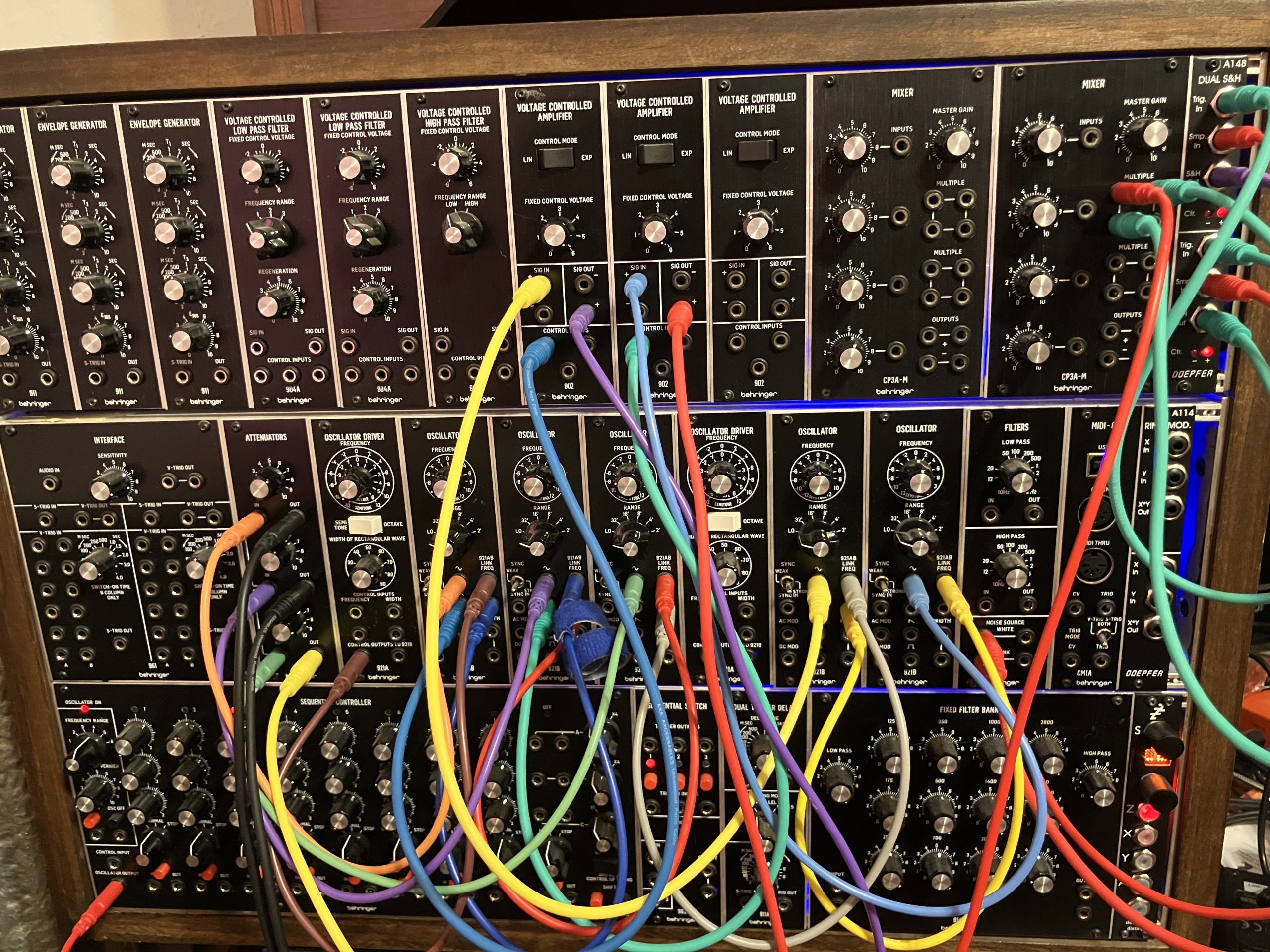
In this experiment I wanted to focus on smooth, flowing changes. Hence, my use of sine waves, which lends the resulting video a wiggly nature. However, in order to send voltages to all seven the Hypno’s CV inputs, I took a different approach with the remaining two signals. Namely I used the oscillator output of the step sequencer. This can be thought of as a gate signal that works like a metronome, providing a steady beat. This signal was sent to two different sample and hold circuits. While the dual sample and hold module I have in my setup is not technically from the line of System 55 clones, the original Moog System 55 did feature a sample and hold circuit.
So, what is a sample and hold circuit? You feed it an input, and a gate signal. Every time the module receives a gate signal, it samples the voltage at the input at that moment, and it holds the output signal at that level until the next gate signal is received. The most common usage of a sample and hold circuit is to feed it a noise signal, which is essentially random voltages. When used in this manner the module produces steady, but random voltages that change at a steady pulse.
That is exactly what I did here, except I fed one of the sample and hold circuits pink noise while I fed the other white noise. Pink noise has less high frequency content than white noise. The result of this difference is that a sample and hold circuit being fed pink noise will have a more limited range of output than one using white noise. Regardless, the two sample and hold circuits produce instantaneous (sudden) changes which were then sent to the Hypno.
Just as had happened with the making of my Star Spangled Banner video, the HDMI connection between the Hypno and my HDMI to USB capture card frequently broke. Thus, rather than generating a continuous twenty and half minute video, I generated five different videos ranging in length from about a minute and a half to ten minutes long. I generally arranged the video from most heavily manipulated to least manipulated. Throughout the video I feel that there are moments where one can recognize that the source video is sunlight glinting off of ocean waves. As stated earlier, my next video experiment will also use control voltages for automation, and will use the results of this experiment as the video input, so you’ll want to stay tuned for that.